Share
Pin
Tweet
Send
Share
Send
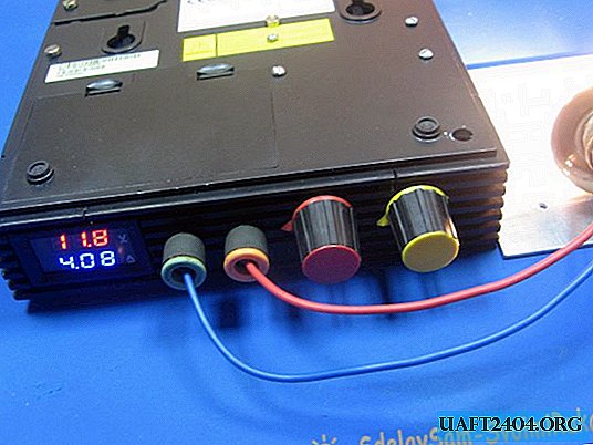
I decided to redo my laboratory power supply. Although it is reliable, it is heavy and takes up a lot of space. The desktop is always lacking. When planning a reshuffle. I decided to hang a hinged shelf and under it is full of space. The idea came quickly, I make a mounted laboratory power supply.
Will need
The case I will have a box from the old modem. It is full of space, and I will collect it on modules.

The power unit is a module from China. The output of the module is 24 volts and they promise an impressive current, as for the dimensions of the module.

I will regulate the output voltage with the help of a ready-made module. The module is quite common, there is a lot of information about it, the price is very good.

Instead of tuning resistors, I will install adjusting, domestic. It’s better to take wire resistors, of course, but I’ll apply what I have. You also need to pick up pens on them.

I have a network toggle switch T3, I have them with a shaft.

The terminals are needed in different colors, so as not to confuse when connecting devices.

Multimeter from China. Very well established. Dimensions just right.

Production of a laboratory unit from Chinese modules
On the body, I make markings for the elements of the front panel. Cut out. The plastic is quite soft, can be cut with a sharp knife.

Trying on a place for the modules. I drill holes and install the modules. I install the network module on the bushings. Bushings cut from a silicone tube. I immediately screwed the output wires from the network module. He carried out the wires for the adjustment resistors. It makes no sense to draw a diagram; everything is corny simple. From the network module, the wires go to the adjustment module. The wires go to the terminals through a multimeter.

Soldered wires to resistors. Found pens of different colors. There are 3 wires to the current control resistor, to voltage 2.

The network wire soldered to the toggle switch. From the toggle switch, the wires go to the module. A very convenient place was under the toggle switch.

I used a stabilizer to power the multimeter. Assembled stabilizer on TL431. You can not put it, but decided to play it safe. It can be powered from 24 volts. The stabilizer can be calculated on the Internet.

For smooth adjustment, in parallel with the adjustment resistor, I installed a constant resistor of 27 kOhm.

Connected input and output wires to the control module. The stabilizer for the multimeter was also screwed to the module. The stabilizer filled thermo with glue.

I close it. I turn it on. I connected the car lamp to the output. Stabilization works fine.

Laboratory power supply fits perfectly in the workshop. Does not take up space. Convenient to use
Links to modules:
- Multimeter DC 100V 10A - //ali.pub/3llsqs
- 300 W DC-DC Converter - //ali.pub/3llsry
- Switching power supply AC 85-265V to DC 24V 4A-6A 100W- //ali.pub/3llsw8
Share
Pin
Tweet
Send
Share
Send

